Quick Overview
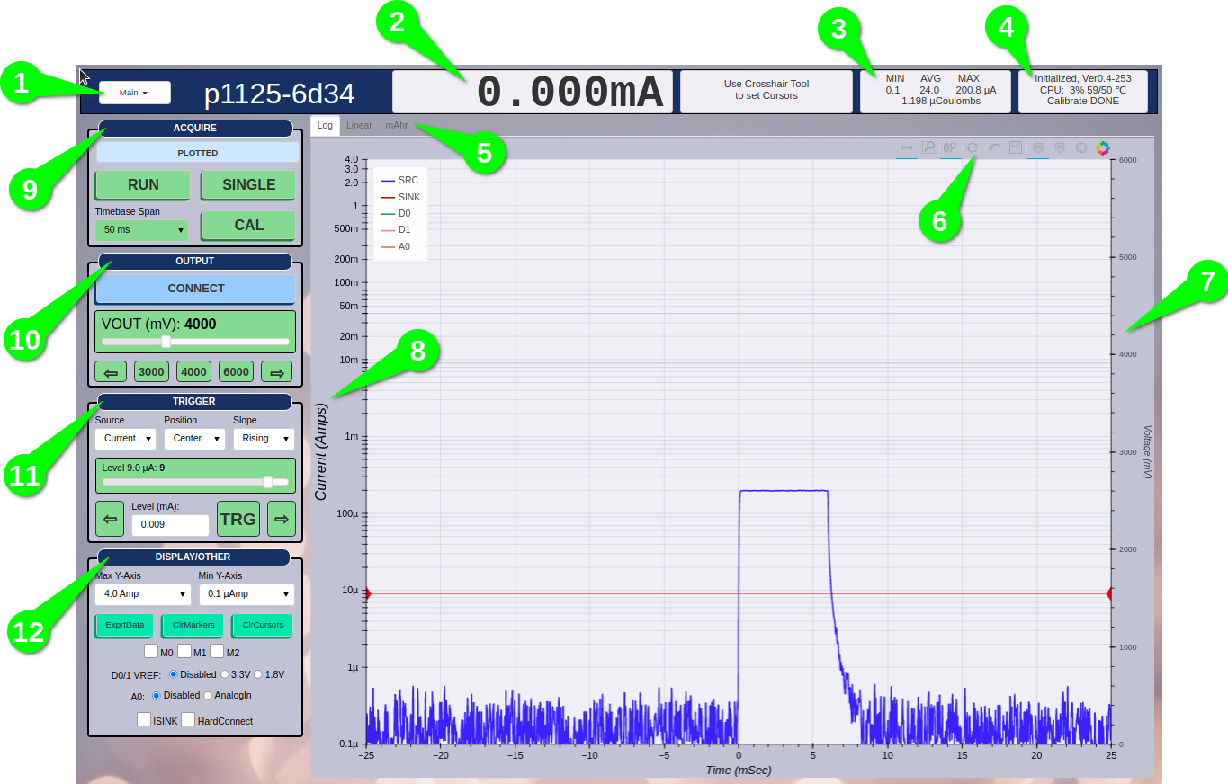
Main Menu
Ammeter - Shows the average current for the last ~1s.
Plotted Stats - Shows stats for the currently plotted waveform.
Status
Plot Tabs - Select to view plot.
Plot Controls - Select tools as required, Reset to original Zoom.
Analog Input A0 Y-Axis
Current Y-Axis
Aquire Controls
Output Controls
Trigger Controls
Display and Other Controls
Note
If the left side control panels do not fit the browser window, press CTRL-/+ to adjust the Zoom level of the browser window.
Acquire Controls
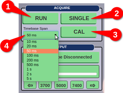
RUN - Starts continuous acquisitions.
SINGLE - Starts a single (one time) acquisition.
CAL - Start Calibration.
TIMESPAN - Select the desired time span of the acquisition.
Note
When P1125 session begins, the CAL button must be pressed before any acquisitions can begin.
Note
Some long Timespan values only support SINGLE acquisition mode.
Output Controls
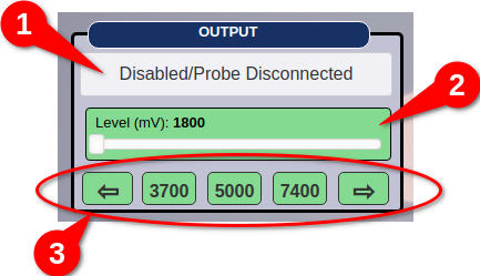
Probe Connect/Disconnect - Connect or Disconnect from the DUT. The probe must be connected to the P1125 for this button to be accessible.
Voltage Slider - Slider to set the Output Voltage.
Voltage Quick Sets - Shortcut buttons to adjust voltage up/dn or to a preset value.
Trigger Controls
Arming the Trigger only affects the (realtime) Log/Lin plots. Trigger does not affect the mAhr plot. Regardless of a trigger, the mAhr plot will always plot.
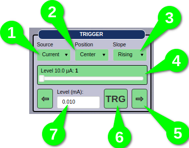
Source - Selects the trigger source.
Position - Set the time zero position on the plot.
Slope - Set the slope of the source waveform which to trigger on.
Slider - Adjust the trigger level. For Log plots the adjustment is within a decade.
Left/Right Arrows - Fine level adjustment.
Manual Trigger - Press to cause a manual trigger. This is useful to locate the signal.
Text Entry - Enter the trigger level in mAmps.
Note
Trigger Source will only show the enabled trigger sources, therefore in order to select auxiliary input triggers, A0, D0, or D1, they must first be enabled.
Display/Other Controls
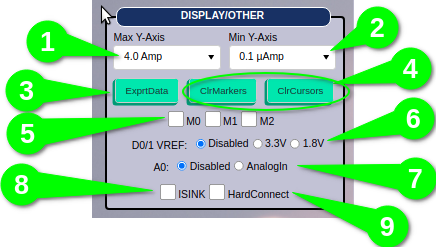
Max Y-Axis - Select maximum Y value for the Log/Lin plot areas.
Min Y-Axis - Select minimum Y value for the Log/Lin plot areas.
ExprtData - Export plot data to a file. See TBD.
ClrMarkers/ClrCursors - Clear Markers, Clear Cursors group.
M0/M1/M3 - Memory Group. Selecting a memory slot will copy the current waveform into memory and keep it plotted to allow for comparison.
D0/1 Vref - Digital input enable and voltage reference selection.
A0 - Set the analog input channel mode.
ISINK - Set whether to display sink current. The p1125 will always sink current, but plotting that current is optional with this control.
HardConnect - When set, VOUT is applied when CONNECT to the target. By default this setting is disabled and P1125 uses a soft start VOUT CONNECT to avoid high in-rush currents. Warning that high in-rush currents are possible with this setting and may trigger source over current.
Plot Area
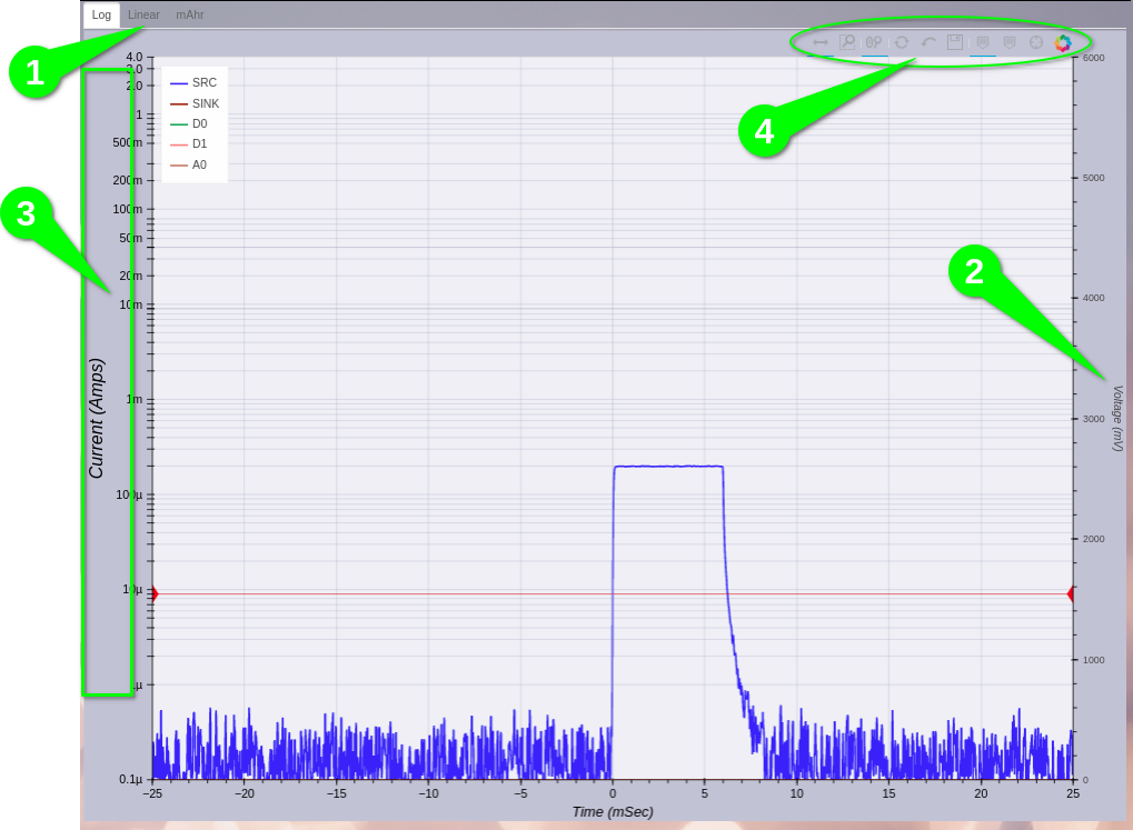
Plot Tabs - Log, Linear and mAhr plots.
Analog A0 Y-Axis.
Set Current Trigger Level Area - When Trigger Source is Current, clicking this area will set the trigger level.
Plot Tools - various zoom, pan, hover and crosshair tools.